22 Results
View results:
Sort by:

The design of cross-sections according to Eurocode 3 is based on the classification of the cross-section to be designed in terms of classes determined by the standard. The classification of cross-sections is important, since it determines the limits of resistance and rotation capacity due to local buckling of cross-section parts.
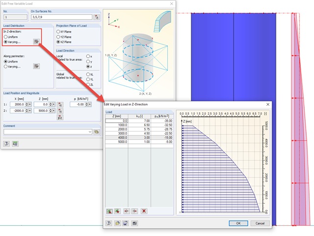
In order to apply loads that are variable in height and perimeter to rotationally symmetric objects, RFEM provides the free variable load.

If members aligned in space meet in a node, the local x- or y-axes of the members do not lie in one plane, since the local z-axes are aligned in the plane of gravity.

For a timber connection as shown in Figure 01, you can take into account the torsional spring rigidity (spring stiffness for rotation) of the connections. You can determine it by means of the slip modulus of the fastener and the polar moment of inertia of the connection.

In RF‑/STEEL EC3, you can assign the same input data to several members or sets of members at the same time. The simultaneous assignment of the input data is possible for intermediate supports, effective lengths, nodal supports, member end hinges, and shear panel and rotational restraint.
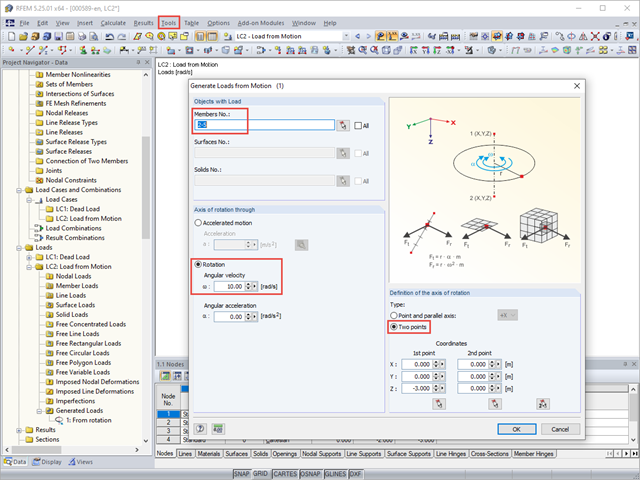
With RFEM, you can generate member, surface, or solid loads resulting from motions. Thus, for example, braking or acceleration forces can be generated automatically from linear movements or from rotational movements on a structural system.

In RFEM 5 and RSTAB 8, it is possible to assign nonlinearities to member hinges. In addition to the nonlinearities "Fixed if" and "Partial activity", you can select "Diagram". If you select the "Diagram" option, you have to specify the according settings for the activity of the member hinge. For the individual definition points, it is necessary to specify the abscissa and ordinate values (deformations or rotations and the according internal forces) that define the hinge.

In the case of open cross-sections, the torsional load is removed mainly via secondary torsion, since the St. Venant torsional stiffness is low compared to the warping stiffness. Therefore, warping stiffeners in the cross-section are particularly interesting for the lateral-torsional buckling analysis, as they can significantly reduce the rotation. For this, end plates or welded stiffeners and sections are suitable.

The classification of cross-sections is intended to determine the limits of resistance and rotational capacity due to local buckling of cross-section parts. In EN 1999‑1‑1, 6.1.4.2 (1), four classes are defined.
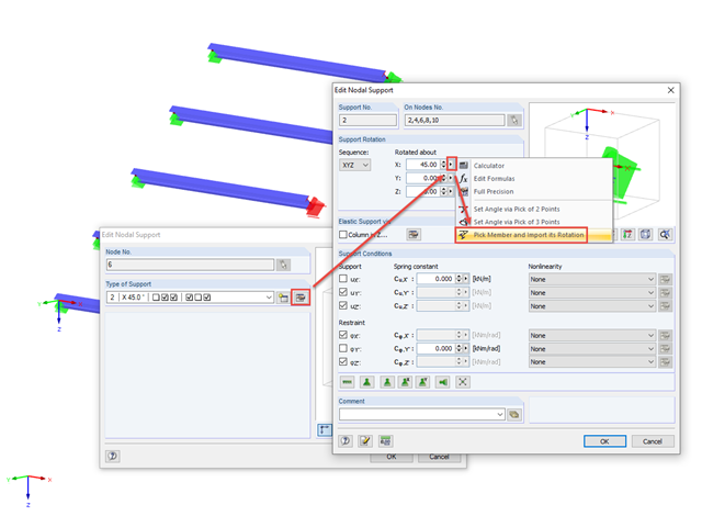
If you want to orient a nodal support to the member axes of the connecting member, the easiest way to do this is to use the "Pick Member and Import its Rotation" function.
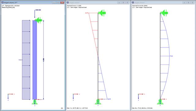
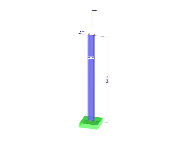
In this technical article, a hinged column with a centrally acting axial force and a linear load that acts on the major axis are designed according to EN 1993-1-1 with the aid of the RF-/STEEL EC3 add-on module. The column head and column base are assumed as a lateral and torsional restraint. The column is not held against rotation between the supports. The cross-section of the column is an HEB 360 from S235.
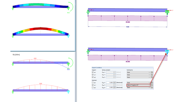
In practice, an engineer often faces the task of representing the support conditions as close to the reality as possible in order to be able to analyze the deformations and internal forces of the structure subjected to their influence and to enable construction that is as cost efficient as possible. RFEM and RSTAB provide numerous options for defining nonlinear nodal supports. This second part describes the options for creating a nonlinear support for a restraint and provides a simple example. For a better understanding, the result is always compared to a linearly defined support.
Using RF-/FOUNDATION Pro, it is possible to perform geotechnical design according to EN 1997-1 [1] for single foundations. The following article explains the design of highly eccentric loading in the foundation core according to DIN EN 1997‑1, A 6.6.5 (see [3]).
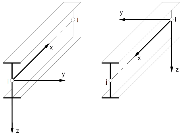
In spatial structures, the member position plays an important role in terms of determining internal forces. The orientation of member axes can be defined either by a global cross-section rotation angle, or by a specific member rotation angle. These two angles are added to determine the position of the main axes of a member in a 3D model.
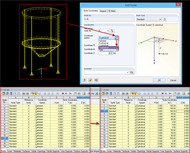
Rotation-symmetric structures or structural components are frequently entered in the Cartesian coordinate system. For example, subsequently changing the radius requires some effort, as the coordinates should be recalculated first and then updated for each node.

If you want to connect members tangentially to a curved member or a curved surface in RFEM, it is necessary to define the member rotation of the connected members. In order to avoid manual determination, you can display the center point of the curved line and place a node on it. Then, you can select the "Member Rotation via Help node" option and specify the relevant help nodes. Thus, the members are rotated automatically in the defined plane (x-z in our example) and the top edge of the rotated cross-section is parallel to the tangent of the curved line.

Prior to the analysis of steel cross‑sections, the cross‑sections are classified according to EN 1993‑1‑1, Sec. 5.5, with respect to their resistance and rotation capacity. Thus, the individual cross-section parts are analyzed and assigned to Classes 1 to 4. The cross-section classes are determined subsequently and usually assigned to the highest class of the cross-section parts. If plastic resistance is to be applied to further design of cross-sections of Class 1 and Class 2, you can analyze the elastic resistance of cross-sections as of Class 3. In the case of cross-sections of Class 4, local buckling already occurs before reaching the elastic moment. In order to take this effect into account, you can use effective widths. This article describes the calculation of the effective cross-section properties in more detail.
The RF-/STEEL EC3 add‑on module performs a detailed cross‑section classification on each design before the design is carried out. Thus, the susceptibility to local buckling of all cross-section parts is evaluated. The defined cross-section class has an effect on the resistance and rotational capacity determination.
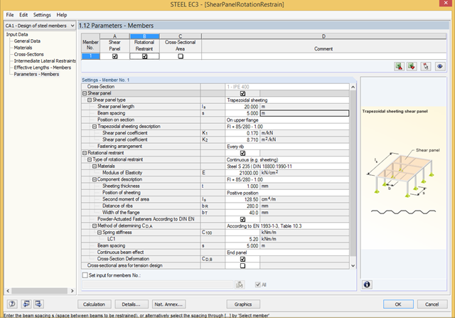
To stabilize the components bearing stability risks, a shear panel and/or a rotational restraint can be defined in RF‑/STEEL EC3. Optionally, trapezoidal sheets, bracings, or individual purlins can be taken into account.
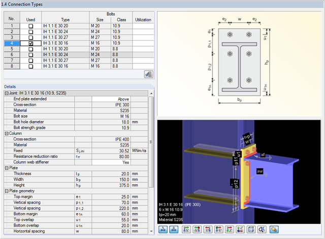
Starting with version X.05.0018, you can also analyze moment-resistant beam-column connections in RF‑/JOINTS Steel - DSTV. Both single-sided and double-sided connections are possible. In compliance with the DSTV guidelines, the program checks (with respect to the loading) whether the existing column cross‑section is dimensioned sufficiently. Optionally, you can transfer the rotational stiffness and the eccentricity of the connection to RFEM or RSTAB.
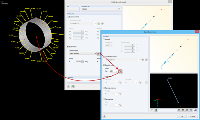
When defining nodal loads, you can rotate the load using several simple options: ~ Rotation by angle around the global coordinate axes in a specific order, ~ Alignment with a user-defined coordinate system, ~ Direction to a particular node, ~ Alignment by means of two nodes, ~ In the direction of a member/line.
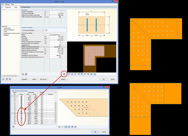
In RF‑/JOINTS Timber, you can remove an individual dowel from the calculation, thus creating any dowel layout. The calculation disregards these removed dowels for the ultimate limit state design, as well as for the net timber cross‑section analysis and the rotational spring stiffness determination.